Carrier Rollers (Top Roller) for Excavators and Crawler Undercarriages
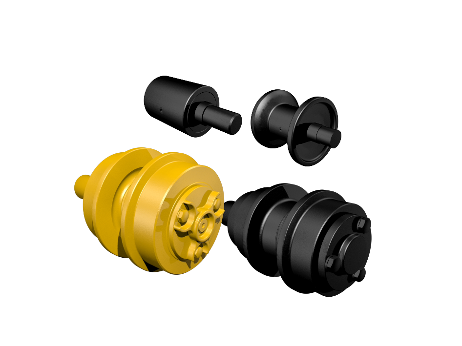
Carrier rollers for excavators and crawler undercarriages are identified by reference number, machine model, mounting position, fastening and component dimensions. They are installed in the upper section of the undercarriage and support the upper track return.
- Selection by reference number, machine model and mounting position
- for excavators, mini excavators and crawler undercarriages
- technical identification by fastening, mounting interface and component dimensions
📞 +49 (0)2241 26 56 700
Carrier Rollers (Top Roller) for Excavators and Crawler Undercarriages
Carrier rollers for excavators and crawler undercarriages are identified by reference number, machine model, mounting position, fastening and component dimensions. They are installed in the upper section of the undercarriage and support the upper track return.
- Selection by reference number, machine model and mounting position
- for excavators, mini excavators and crawler undercarriages
- technical identification by fastening, mounting interface and component dimensions
📞 +49 (0)2241 26 56 700
Search for machines (e.g. Komatsu PC200 LC-7)


Correctly identifying carrier rollers in crawler undercarriages
Carrier rollers are installed in the upper section of the crawler undercarriage and support the upper track return. They influence the path of the track chain above the track frame and are therefore a relevant component of the upper undercarriage guidance system.
For spare parts identification, the machine designation alone is not sufficient. The relevant points to check are reference number, machine model, mounting position, fastening, mounting interface and existing component dimensions. Especially on machines with different series, undercarriage versions or varying fastening designs, the existing carrier roller should be compared with the product data, existing component dimensions or, where available, a technical drawing.
Carrier roller, top roller and upper roller terminology
Depending on supplier, catalogue or data source, carrier rollers may also be referred to as top rollers, upper rollers or, in German product data, Tragrollen and Stützrollen. The term refers to the upper roller in the track undercarriage that supports the upper track return. These terms are relevant for identification, but the correct selection should always be based on machine model, mounting position and reference number.
A clear distinction from the track roller is important. Track rollers work in the lower track run and are more directly related to load support and ground contact of the undercarriage. Carrier rollers work in the upper section of the undercarriage and are relevant for the upper track return. In international product data, Track Roller, Bottom Roller and Lower Roller are mainly used for lower track rollers. Carrier Roller, Top Roller and Upper Roller refer to the upper undercarriage roller.
Selection by reference number, mounting position and fastening
In spare parts practice, the reference number is the most important starting point for identification. In addition, machine model, mounting position and undercarriage version must be checked, because similar machines may use different carrier rollers depending on series, year of manufacture or equipment version.
Depending on the design, fastening, mounting interface, axle, roller diameter, overall width and other component dimensions may also be relevant for correct identification. If the version is not clear, the installed carrier roller should be compared with the removed component, the product data or, where available, a technical drawing.
Carrier rollers in relation to the track chain, idler and sprocket
Carrier rollers do not operate in isolation. They work as part of the undercarriage system together with track chains, rubber tracks, idlers, sprockets and track adjusters. Changes in the upper track return, unstable track movement or an unusual contact pattern should therefore always be assessed in relation to the complete undercarriage.
Depending on the machine, carrier rollers may be used in undercarriages with steel tracks or rubber tracks. The correct assignment should not be derived from the track type alone, but from reference number, machine model, mounting position and existing component geometry.
Checking wear on carrier rollers
The condition of a carrier roller should be assessed across several inspection points. Relevant factors are running surface, roller diameter, guide areas or flanges where present, sealing area, rotation behaviour, fastening and contact pattern with the upper track return. Typical signs of advanced wear include reduced roller diameter caused by worn running surfaces, damaged or thinned guide areas, scoring, clear lubricant leakage, stiff-running rollers or blocked rollers.
A light oil film in the sealing area is not automatically the same as function-critical leakage. It should be assessed whether there is clear lubricant leakage with adhering dirt, stiff rotation, a blocked roller or other visible irregularities.
An unusual wear pattern on carrier rollers may be related to lateral load, angled travel, frequent turning under load, incorrect track tension, dirt accumulation in the upper undercarriage area or unfavourable undercarriage alignment. In such cases, not only the individual carrier roller should be checked, but also the track, track frame, idler position, sprocket and track adjuster.
Carrier rollers as part of undercarriage inspection
Replacing individual carrier rollers is often part of a broader undercarriage assessment. If several carrier rollers show a similar wear pattern or the upper track return runs visibly unevenly, track rollers, track chains, track shoes, rubber tracks, idlers, sprockets, track adjusters and fastening components should also be checked.
To select the correct LIS® carrier roller, reference number, machine model, mounting position, fastening, mounting interface and existing component dimensions should be compared. If identification is unclear, comparing the part with the removed component or, where available, a technical drawing is recommended.
📞 +49 (0)2241 26 56 700